Blocks
Note
Blocks are combined to build control chains to run on the Brewblox Spark.
In the UI, they can be displayed by widgets on a dashboard. For more information on blocks vs widgets, see the Blocks architecture guide.
For a description of widgets, see the widgets page.
Block data reference documentation for developers can be found here.
Sensors
Sensors measure something. Currently we only have sensor blocks for temperature.
OneWire Temp Sensor
OneWire sensors are identified by address and can be automatically discovered. They can be plugged into a connected expansion board, or directly into the Spark itself.
To look for new sensors, go to the service page of the Spark and click on 'Discover new OneWire blocks' in the top right menu.
You can apply a calibration offset to a OneWire sensor in its settings.
Temp Sensor (Mock)
This is a simulated sensor that allows you to manually set the 'measured' value. You can use it to play with the system, to see how it will respond.
Temp Sensor (Combined)
Sensor values can be aggregated using this block. You can set multiple sensors as input, and choose whether to set output to the average, min, or max value of the linked sensors.
Temp Sensor (External)
Not all temperature sensors can be connected directly to the Spark. This block lets you set sensor values explicitly, with the added fail-safe protection of a timeout. If the timeout period is exceeded between value updates, the sensor becomes invalid.
Setpoints
A Setpoint holds the target value for a specific sensor. It used as input for a PID.
Each Setpoint has a link to a sensor. The Setpoint provides the PID with averaged sensor values to filter noise. How many values are averaged is set by the Filter period. The filter can be bypassed to respond faster when the filtered value differs too much from the current value. The bypass threshold sets the difference at which this happens.
Setpoint Profile
If you want to slowly change a Setpoint over time, you can use the Setpoint Profile block.
You configure it by setting a temperature value at specific dates / times. The firmware will calculate the values between those two points and gradually change the target Setpoint.

In the example above, the Setpoint Profile is between point 1 and 2, changing temperature from 0°C to 50°C. It is about halfway, so the Setpoint is set to 27.27°C.
All points are saved as an offset from the start time, so you can easily re-use profiles. Change the start time, and all other points will be shifted. You can also create, load, and save profiles from the action menu.
The profile is stored on the Spark itself. The Setpoint Profile continues to run if the Spark has no connection to the server.
When the Spark loses power, it forgets the date and time. The profile is on hold until the Spark reconnects and receives the actual date and time.
Digital Actuators
Actuators act on things in the real world, like temperature or water flow. Digital actuators turn things ON or OFF: a heater, cooler, pump or valve. For all of these, the Digital Actuator block can be used.
A few blocks provide digital output channels. These blocks are Spark Pins, DS2413 Chip, DS2408 Chip, and OneWire GPIO Module. They are automatically detected and represent hardware elements. If you wish to have a digital actuator that is not linked to physical pins, you can also use the Mock Pins block.
A Digital Actuator is a software block that manages a single digital output channel. The Minimum ON time, Minimum OFF time, and Mutually exclusive constraints can be set.
Spark Pins
The Spark 2 Pins / Spark 3 Pins block is a system block and cannot be deleted. Through this block, the (physical) green digital outputs on the Spark itself can be used.
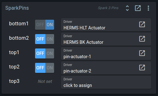
Digital output channels can't be toggled without a Digital Actuator block, but the Spark Pins widget will show the current state of driving actuators. If you click on the toggle button here, it will toggle the desired setting in the actuator.
On the Spark 3, you can also see the current values of the 5V and 12V power supply. Putting 12V on the RJ12 connectors can be enabled or disabled here. If you don't have motor valve expansion boards, leave it disabled to avoid any damage if things are connected wrongly.
OneWire GPIO Module
On the Spark 4, IO is more flexible, with the possibility of attaching up to four GPIO extension modules. Such modules are represented by the OneWire GPIO Module block.
Like the Spark 2 Pins / Spark 3 Pins blocks, digital output channels are listed here. Where the Spark 2/3 channels were fixed, GPIO module channels can be customized for specific device types.
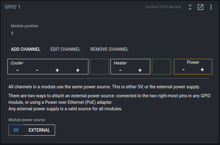
Channels can be freely assigned to the physical IO pins. In the below screenshot, the Ferment cooler channel is mapped to pins 1 and 2, and Ferment glycol to pins 3 and 4.
To change pin assignment, you can click the channel and select its new start position.
Multiplication
There is a maximum of 1A per + pin. If you have a motor that draws 2.5A, you will have to multiply the pins x3 in the channel settings, and then connect the 6 pins (3x -, 3x +) to your motor.
Alternatively, you can multiply the pins to control parallel devices with the same digital actuator.
Polarity
When assigned, the Widget shows the - / + / GND / PWR mapping of the pins within the channels. - pins are always on the left side, and + pins on the right side. If the channel is multiplied, all - pins will be to the left, and all + pins to the right.
DS2413 Chip
The DS2413 is used on the SSR extension board and DC Switch extension board. It makes two extra digital outputs available for use via OneWire. Channel A and B can be used as target for Digital Actuator blocks.
This block is added by clicking 'Discover new OneWire block' in the Spark service page menu.
DS2408 Chip
The DS2408 is used on the Motor Valve Expansion board. It has 8 channels, which can be used by 8 Digital Actuator blocks, or by two Motor Valve blocks: each Motor Valve requires four channels.
This block is added by clicking 'Discover new OneWire block' in the Spark service page menu.
Motor Valve
The Motor Valve functions like a Digital Actuator, but is a special block to be used with our Motor Valve expansion board and the DS2408 Block. The board uses 4 channels per valve to drive the motor bidirectionally and to read open/closed feedback pins.
If you use valves that take a single digital signal, like solenoid valves for example, you should just use the Digital Actuator block. Both the Digital Actuator and the Motor Valve block can be linked to a valve in the Brewery Builder.
The Motor Valve block can be claimed by a PWM block. It also supports the Minimum ON, Minimum OFF, and Mutexed constraints.
Mock Pins
Used for testing, or in combination with the Logic Actuator block, there also is the Mock Pins block. It has 8 virtual channels that can be used as target for a Digital Actuator.
Analog Actuators
Analog actuators have a numeric output value, between a minimum and maximum. A PID requires an analog actuator as output.
We currently have three types of analog actuator:
- PWM
- Setpoint Driver
- Analog Actuator (Mock)
The Minimum, Maximum, and Balanced constraints can be set on all analog actuator blocks.
PWM
Digital Actuators can only be turned ON or OFF. But by turning them on and off repeatedly, you can run them at 20% or 50% on average over a certain time. This is the function of the PWM block. It toggles a Digital Actuator target repeatedly to achieve an average ON percentage. The duration of each ON-OFF cycle is the period.
PWM stands for Pulse Width Modulation.
Example
The period is configured to be 4 seconds. When the PWM actuator is set to 40% it will turn the target ON for 1.6 seconds and OFF for 2.4 seconds and repeat. So the output is repeatedly pulsed, with a changing (modulated) pulse width.
This turns a digital ON/OFF actuator into an 'analog' actuator with a range between 0% and 100%.
Note: The PWM block keeps a short history of when it toggled and tries to maintain the correct average. To do this it can make a period a bit longer or shorter than what is configured.
Fast PWM
The normal PWM + Digital Actuator combination works for PWM periods longer than a second. For high-frequency PWM, a different implementation is required.
The Fast PWM block supports periods between 0.5ms (2000Hz) and 12.5ms (80Hz). To do this, the block directly controls an IO channel, without the intermediate Digital Actuator block.
OneWire extension boards such as the DS2408 and DS2413 do not support Fast PWM. They simply can't be toggled fast enough.
Setpoint Driver
Sometimes a temperature is best controlled indirectly by managing another temperature. An example is a HERMS system, where the mash temperature interacts with the HLT temperature.
The Setpoint Driver block turns the difference between two temperatures into an actuator.
Lets look at the HERMS example.
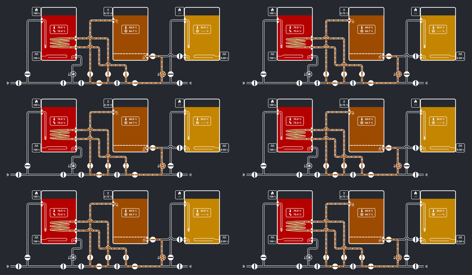
The wort in the mash tun (MT, middle) is picking up heat when it flows through the HERMS coil in the hot liquor tun (HLT, left). The water in the HLT is warmer than the wort in the MT. The wort will come back to the MT at a temperature close to that of the water in the HLT.
Directly using the MT sensor as input for the HLT heater can result in too much overshoot, or a slowly reacting system. Because of the long delay between heating the HLT and measuring the effect in the MT, heating has to be slow to give the process time to respond.
If we control HLT temperature in relation to the MT temperature, we can have more control over the system. We can heat the HLT to a temperature above the desired mash temperature if we know that the extra heat in the HLT can eventually be transferred to the MT without overshoot.
Brewblox lets you build this scenario using two PIDs:
- One PID will directly control the HLT temperature, using the HLT sensor, HLT setpoint, and HLT heater.
- One PID will continuously change the HLT setpoint to the value that will get the wort in the MT to the desired temperature as quickly as possible without overshoot. This PID will have a Setpoint Driver as output.
In the example above the MT setpoint is 66.7 °C. The PID calculated that HLT setpoint should be 6.72°C higher than the MT setpoint. The Setpoint Driver applied this by changing the HLT setpoint to: 66.7°C + 6.72°C = 73.4°C.
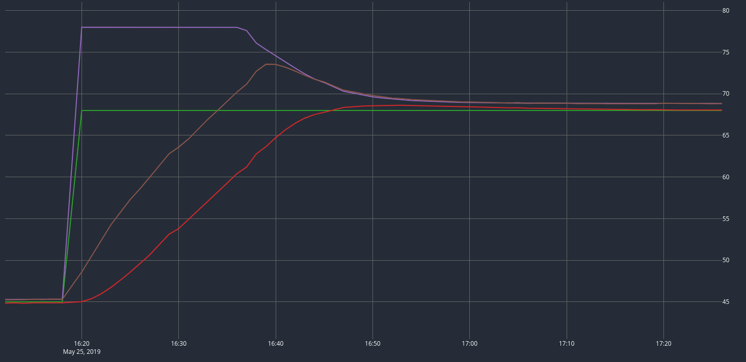
The effect of a driven HLT setpoint can be seen in the graph below. With the MT temperature well under MT setting, the HLT setting was set to its maximum.
The HLT was heated quickly until its temperature approached the setting. When the MT temperature approached the MT setting, the HLT setting was lowered to minimize overshoot.
This combination of control blocks is generated by the HERMS wizard. More details and an example of the Setpoint Driver in a fermentation fridge are described in the control chains guide.
Analog Actuator (Mock)
This is a dummy actuator that is mostly used for testing and development.
Digital Actuator Constraints
Digital actuators can have constraints that limit when they can turn on or off. Minimum OFF time, Minimum ON time, Delay ON, Delay OFF, and Mutually exclusive constraints can be set. A minimum on and off time are often used to protect a fridge compressor from overheating.
A digital actuator has a desiredState, set by you or PWM block driving it, and a state, the actual status of the physical pin. Every update tick, the firmware tries to change state to desiredState, if the constraints allow it.
For example: you have a Digital Actuator with a Minimum ON time (10 seconds) constraint, and a current state of OFF.
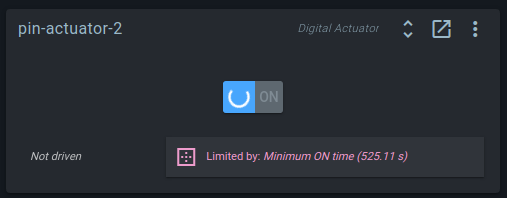
If you toggle the actuator, it will turn on. If you immediately try to toggle it again, it will remain on for 10 seconds, and then turn off. During this period, the widget will display a spinner, and a description of the currently limiting constraint.
Mutex
When two digital actuators should never be active at the same time, they can be constrained with a Mutex. Mutex stands for Mutually exclusive. This can be used to prevent a heating and cooling at the same time, or ensure that two high power heating elements are not both turned on and blow a fuse.
To use a mutex, you first create a Mutex block. It provides the token that actuators have to posess to be allowed to turn on. When they take this token, they lock the mutex for other actuators.
After creating the Mutex block, you can add a Mutually exclusive constraint to each Digital Actuator, with the Mutex block as target.
In the constraint, you can configure the extra lock time setting to hold the mutex for a while after the actuator turns off. This can let a cooler block the heater from turning on for a certain time, to prevent heating too quickly after cooling. When the extra lock time is not set in the constraint, the duration falls back to the default, which is set in the Mutex block.
Note that the mutex limits actuators from turning on at exactly the same time. If you have two heating elements that are driven by PWM, the PWM cycles can overlap. When one turns off, the other can turn on. This makes it possible to run both elements at 50% at the same time! To ensure that they will each take their fair share and not hog the mutex, you should also add a Balancer (see below).
Analog Actuator Constraints
On analog actuators, you can limit the range of the output by adding constraints. You can set Minimum, Maximum, and Balanced constraints.
Analog actuators have 3 values to manage this: desiredSetting, setting, and value.
Desired setting is the number set by either you, or by the PID.
Setting is the number after constraints have have been applied.
Value is the value that has actually been measured. It can differ from the setting if the actuator cannot reach the setting. The target of a PWM Block can have its own constraints that hold it back. The SetPoint Driver uses the measured value of the setpoint, which needs time to reach the desired value.
Balancer
When two actuators need to share a total available amount, the balancer can ensure it is shared fairly.
The most common example is using two heating elements with a Mutually exclusive constraint. The sum of their settings should be limited to 100%.
When a Balanced constraint is set on both PWM blocks, they ask their target Balancer how much they can use. The Balancer scales down their setting proportionally so the sum does not exceed 100%. Without the balancer, a heater with PWM at 100% would never release the mutex to give the other heater some time.
Usage of the Balancer block has its own section in the control chains guide.
PID
The PID block is the block that actually controls a temperature:
- It reads the sensor input
- It compares the measured value with a setpoint
- It then calculates the desired output value for the target actuator
Wikipedia offers a good explanation of how PID controllers work.
The PID has more configuration settings than most other blocks. If this seems daunting, and you just want to keep your fermentation fridge at 18°C: don't worry. QuickStart wizards create preconfigured PID blocks that need little to no changes.
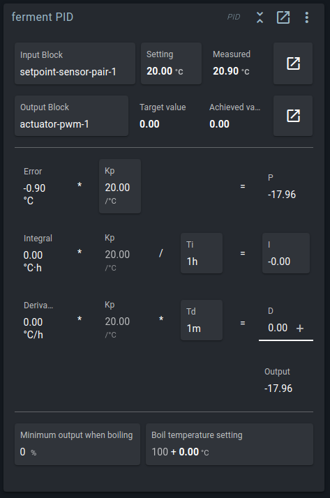
Settings are divided in three sections:
Input / Output
You can choose which Setpoint is used as input here and assign which Analog Actuator is claimed by the PID. By Clicking on the Setting button, you can also directly edit setting of the Setpoint block.
Below the input and output, the math of the PID algorithm is shown.
Proportional
The first equation calculates the proportional part of PID, or P. Kp is called the proportional gain. The difference between the measured value and the setting, the error, is multiplied by Kp. A higher value of Kp will give a higher output value and more agressive correction.
Important
Kp should be positive if the PID controls a heater. Kp should be negative if the PID controls a cooler.
Integral
The second equation calculates the integral part of PID, or I. Every second, the error value is added to the integral. This means that a small error slowly builds up and the integral will inrease over time. The integral value is multiplied by Kp and divided by Ti, the integral time constant. The result is that the time it takes for I to rise to the same value as P is Ti.
The purpose of the integral is to slowly move the process to the desired value, when the process is constantly losing energy to the environment.
Example
When you are fermenting a beer in a cold room, the heater might need to run at 10% to offset the heat lost to the environment. With a setpoint of 20°C and Kp at 20, the actuator will be set to 10% when the beer reaches 19.5°C. At this point the energy added will be equal to energy lost.
Without the integrator, the beer would stay at 19.5°C, but with the integrator, the small error slowly accumulates in the integral and raises the I part of PID. The integral will continue to rise until the error is zero at 20°C.
Ti should be long enough to only affect these equilibrium situations. If Ti is too short, the integral will accumulate before equilibrium is reached and overshoot will happen.
Note that the algorithm does not increase the integral if the output value cannot be achieved by the actuator. This is called anti-windup.
Derivative
The last equation calculates the derivative part of PID, or D. The derivative is the slope of the error. When it is negative, the process is already moving in the right direction and less actuator action might be needed.
The derivative reduces the actuator output to avoid overshoot. Td is the derivative time constant, roughly the duration of overshoot that is expected.
The derivative is taken from a filtered value of the input. The duration over which the derivative is calculated depends on Td.
Boil mode
Boil mode is an optional feature of the PID. Boil mode lets the PID approach the boil temperature at full power and maintain a minimum output when it is reached.
Normal PID behavior is to stop heating when the temperature gets close to the setpoint. When you are boiling, you want to keep heating when the temperature reaches 100°C (212 °F) to maintain the boil.
When the minimum output when boiling is set, the output value will never drop under the configured minimum if the setpoint is at or above the boil temperature.
The minimum output is automatically applied based on the value of the setpoint. If the setpoint is below the configured boil temperature, boil mode does nothing.
Of course, if the minimum output is 0%, boil mode also does nothing.
Logic Actuator
The Logic Actuator allows toggling a Digital Actuator based on a combination of comparisons. Examples of comparisons are: beer temperature >= 20, fridge setpoint <= 10, heater == ON.
For controlling temperature, a PID block is almost always the better choice. The Logic Actuator is for additional behavior while the PID controls the temperature.
Some examples of when the Logic Actuator can be used:
- Multiple fermenters sharing a glycol pump. Each individual fermenter controls a valve connecting its own coil from a shared loop, and the pump should be active if one or more valves are open.
- Turning on a fan in a fridge to circulate the air when either the heater or the cooler is ON.
- Turning on a fan if the PWM setting of a heater is over a limit. The additional air circulation may not be required if the heater setting is below 10%.
- Turning on a warning light if a temperature exceeds a threshold.
Comparisons
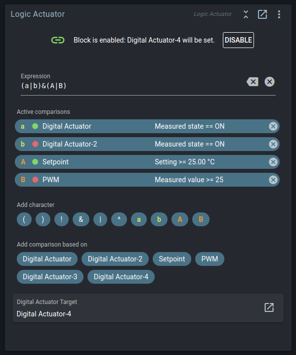
The Logic Actuator claims a Digital Actuator, and evaluates one or more comparisons to determine whether the result is ON or OFF.
You can add comparisons based on Digital Actuator, Motor Valve, Setpoint, and PWM blocks. Each comparison compares the value or setting of the block to a value configured in the comparison. The result is displayed as a green dot for comparisons that are true and red for false.
In the above picture, Digital Actuator and Setpoint have a true result, and Digital Actuator-2 and PWM have a false result.
You can add multiple comparisons that use the same block. To check whether a value is within a range, you can use if value is greater or equal to 25 AND value is smaller or equal to 75.
Digital comparisons can be based on the measured state, the actual digital pin state, or the desired state, the state requested by PWM or the user.
Analog comparisons can be based on the setting, or the measured value. For a setpoint, the setting is the target temperature and the value is the reading from the temperature sensor.
If you want to check ... create a comparison for a ...
- Temperature ⇒ Setpoint
- Output % ⇒ PWM
- Output ON/OFF ⇒ Digital Actuator
- Valve open/closed ⇒ Motor Valve
Expression
You can use multiple comparisons to get the final result.
Each comparison is assigned a reference letter. The letters are combined with ! & | ^ operators and brackets. The string of comparisons, operators, and brackets is called the expression.
! is the logical NOT operator. It is placed before a comparison or sub-expression, and inverts its result. !true is false, and !false is true. (Example: !a)
& is the logical AND operator. The result is only true if both values are true. (Example: a&b , a&b&c)
| is the logical OR operator. The result is true if one of the values or both values are true. (Example: a|b, a|b|c)
^ is the logical XOR operator. The result is true if exactly one of the values is true. (Example: a^b, a^b^c)
( and ) work exactly the same as brackets in maths. Sub-expressions are evaluated first to get a result that is then used in the rest of the expression. (Example: a&(a|b))
Example
In the above image, the expression is (a|b)&(A|B).
Brackets are evaluated first, so we'll start with (a|b).
ais the Comparison for theDigital Actuatorblock. Here it istrue(as shown by the green indicator).bis the Comparison for theDigital Actuator-2block. The red indicator shows this currently evaluates tofalse.true | falseistrue.
The second set of brackets is evaluated next: (A|B).
Ais the Comparison for theSetpointblock. It has a green indicator showing it to be currentlytrue. Apparently, its setting is higher than 25 °C.Bis the Comparison for thePWM. It has a red indicator. Its measured value is below 25%, resulting in afalse.true | falseistrue.
At this point, the expression has been simplified from (a|b)&(A|B) to true & true. This evaluates to true, meaning that Digital Actuator-4 will be turned ON.
Combining logic with constraints
When you use the Logic Actuator to control a fan, it will set the desired state of the Digital Actuator of the fan. You use an expression like a|b, to check that the heater or cooler is turned on.
Next you can set a Delayed ON and a Delayed OFF constraint on that fan actuator. This would cause the fan to start a while after the heater/cooler has turned ON and run for a while after it has turned off.
Sequence
Where the Logic Actuator has a singular condition, and will always toggle a Digital Actuator, the Sequence block executes a list of instructions. Some of these instructions set block settings, and others wait for conditions to be satisfied.
With these instructions, you can automate common tasks on the controller, and create triggers that keep watch in the background.
For example, the Sequence block can be used to:
- Group block changes:
- Toggle between pre-defined flow routes by opening or closing multiple valves.
- Enable or disable the entire system.
- Open or close a valve whenever you start or stop a pump.
- Reset and start a Setpoint Profile start time.
- Chain behavior:
- Set a temperature, wait for your mash to reach target temperature, and then start a Setpoint Profile.
- Turn on a fan, let it run for half an hour, then turn it off again.
- Trigger actions:
- Show a warning light or sound an alarm when your beer temperature is outside the expected range.
- Run a defrost cycle once per day.
The Sequence instructions page describes the syntax and available instructions.
Display Settings
The Spark controller has a LCD screen that can show up to six blocks. Sensors, setpoints, PWMs, and PIDs can be shown on the display.
You can use the Display Settings block to add blocks to the screen and edit how they are displayed. Eligible blocks also have an Add to Spark display action in their action menu (top right button in the widget).